CFD Modelling to Assess Argon Inerting Flow Distribution
The Pile Fuel Cladding Silo (PFCS) is a legacy plant at Sellafield, which was commissioned in 1952. It holds Intermediate Level Waste (ILW) inside six, 21m tall silo compartments, providing a total storage volume of 3200m3 . Each compartment is separated into two chambers by a dividing wall which has a gap at the top and bottom. Between 1952 and 1965, decanning waste (aluminium, graphite and Magnox) was dropped from a covered hatchway into the six silo compartments. Waste retrieval is not scheduled to commence until 2018/2019.
To reduce the risk of fire, a continuous supply of inerting Argon is introduced into each compartment and the purge flow leaves the compartment via a vent in the roof. In the event of a fire, the inlet flow will be increased and flow will exit through a hatch to the tunnel above the compartments. MMI used CFD modelling to assess the inerting flow distribution and gas temperature for multiple inlet configurations under normal operating conditions and for a range of fire conditions.
Critical Issues
The waste material is composed of randomly located items of many shapes and sizes, and appropriate characterisation of the average porosity and resistance was necessary to ensure the correct flow distribution and bed depth penetration of Argon. The effect of fire; its location, intensity and heat conduction through walls and waste material was assessed to identify the resulting gas temperature.
Analysis of the Results
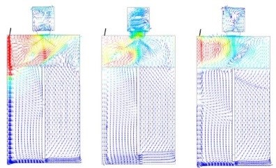
Figure 1 illustrates the flow distribution from the inlet (top left hand corner), in three planes, through the waste material in the two chambers and in the space above the waste material.
Figure 1: Velocity Vectors, Far, Middle and Near Planes – with Fire at Top of Left Chamber
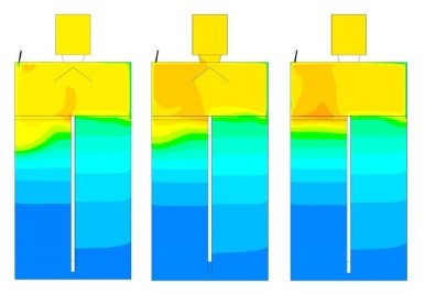
Figure 2 shows the variation of temperature within a compartment subjected to a fire at the top of the left hand chamber.
Figure 2: Temperature Contours, Far, Middle and Near Planes – with Fire at Top
Added Value
CFD analyses were performed to determine the Argon flow distribution and gas temperature for a number of configurations and fire scenarios. Analysis indicated that the single high velocity inlet actually increased the flow resistance through the waste material, therefore reducing the beneficial recirculating through flow. MMI suggested improved inlet configurations, which would reduce the inlet velocity and improve inerting flow through the waste material.
For more information surrounding our project lifecycle experience within the Nuclear Industry, please contact us on 0117 960 2212 (Bristol) or email us.

